Upgrading the Phase 5 Cyberstorm MK2 from 68040 to 68060
This is how to upgrade a Cyberstorm 68040 Accelerator for the Amiga 3000/4000 to 68060.
I got a A4000 motherboard and Cyberstorm MK2 040 sent to me from my friend Klementino from Croatia to be repaired and maybe do something with the Cyberstorm, so why not max it out?
The Cyberstorm Acceleratorcars are the best accelerators for big box Amigas and it for sure is a beaty:

So. first. what do we need to to? well.. we need to move 2 resistors, remove one jumper and do some work to change the CPU voltage from 5V (that the 68040 uses) to 3.3V (that the 68060 uses)
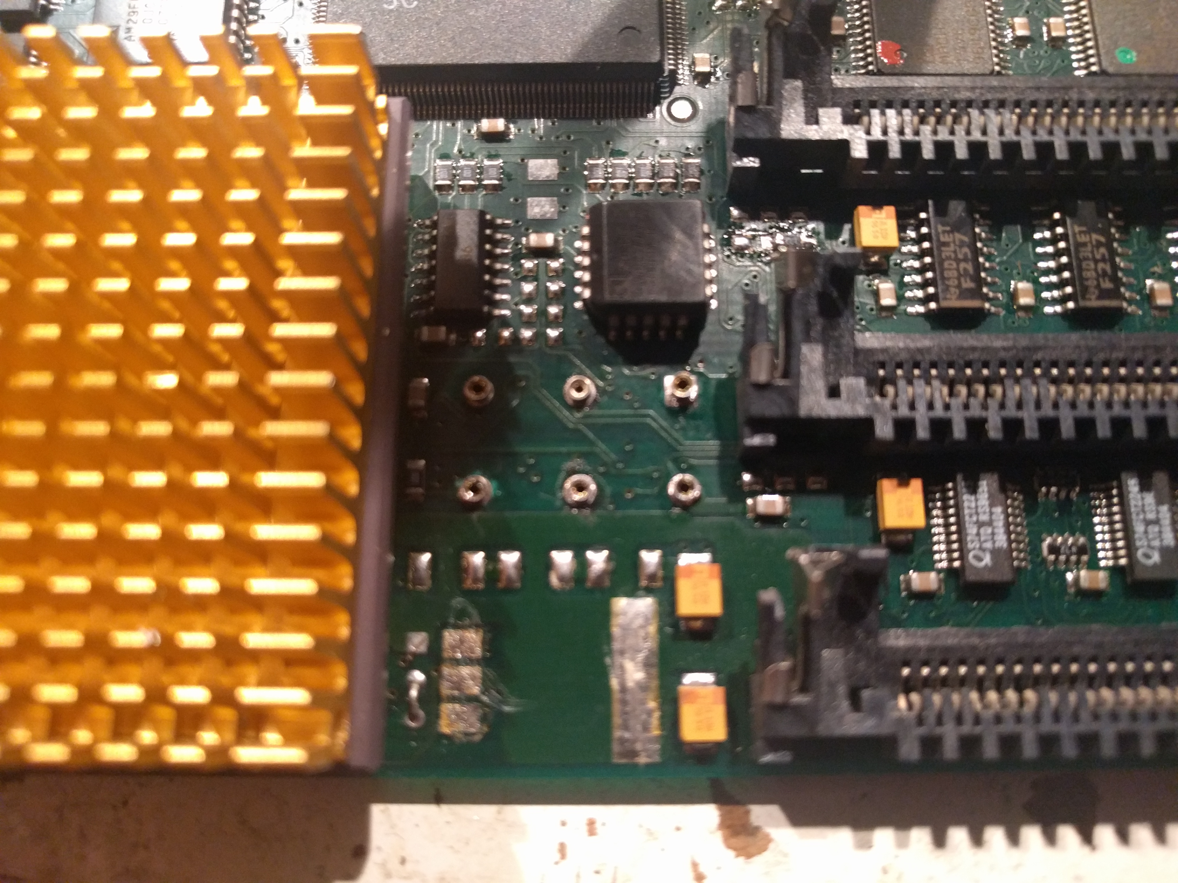
So the areas we need to have some attention to is:
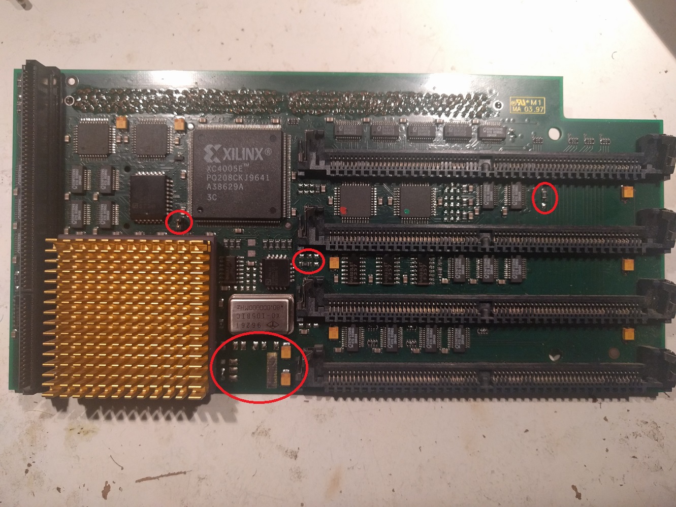
I have marked the areas with red circles.
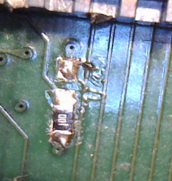
First one resistor. I have called it “jp1″ might be TOTALLY wrong but it is located between the top 2 simmsockets and on a 040 card it is located like:

This you have to move to the other position:
OK when this is done, we take the next one. between the “middle” simmsockets close to the osciallator.
At 040 mode it is like:
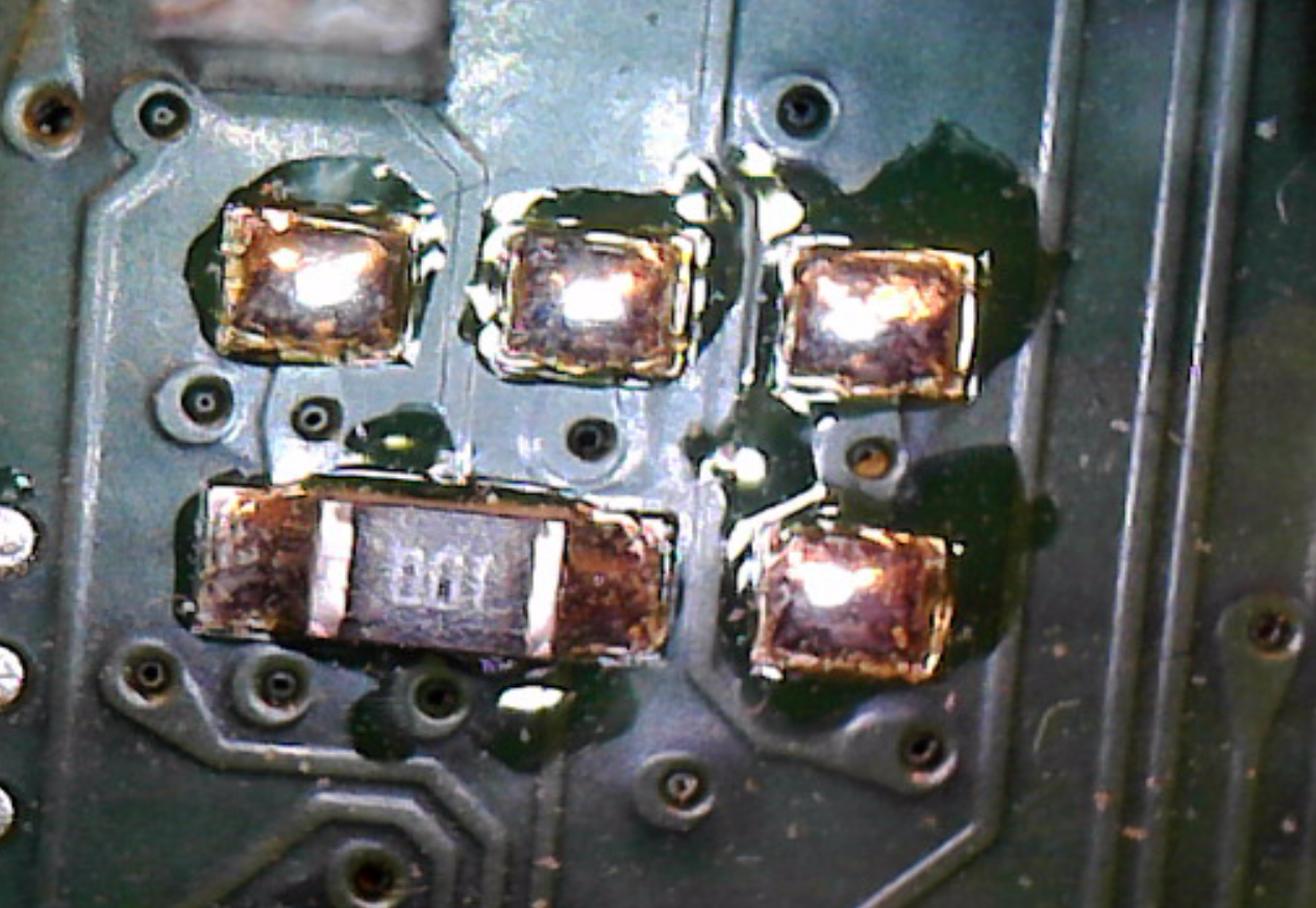
Move this to the right so it looks like:

Then I removed the oscillator
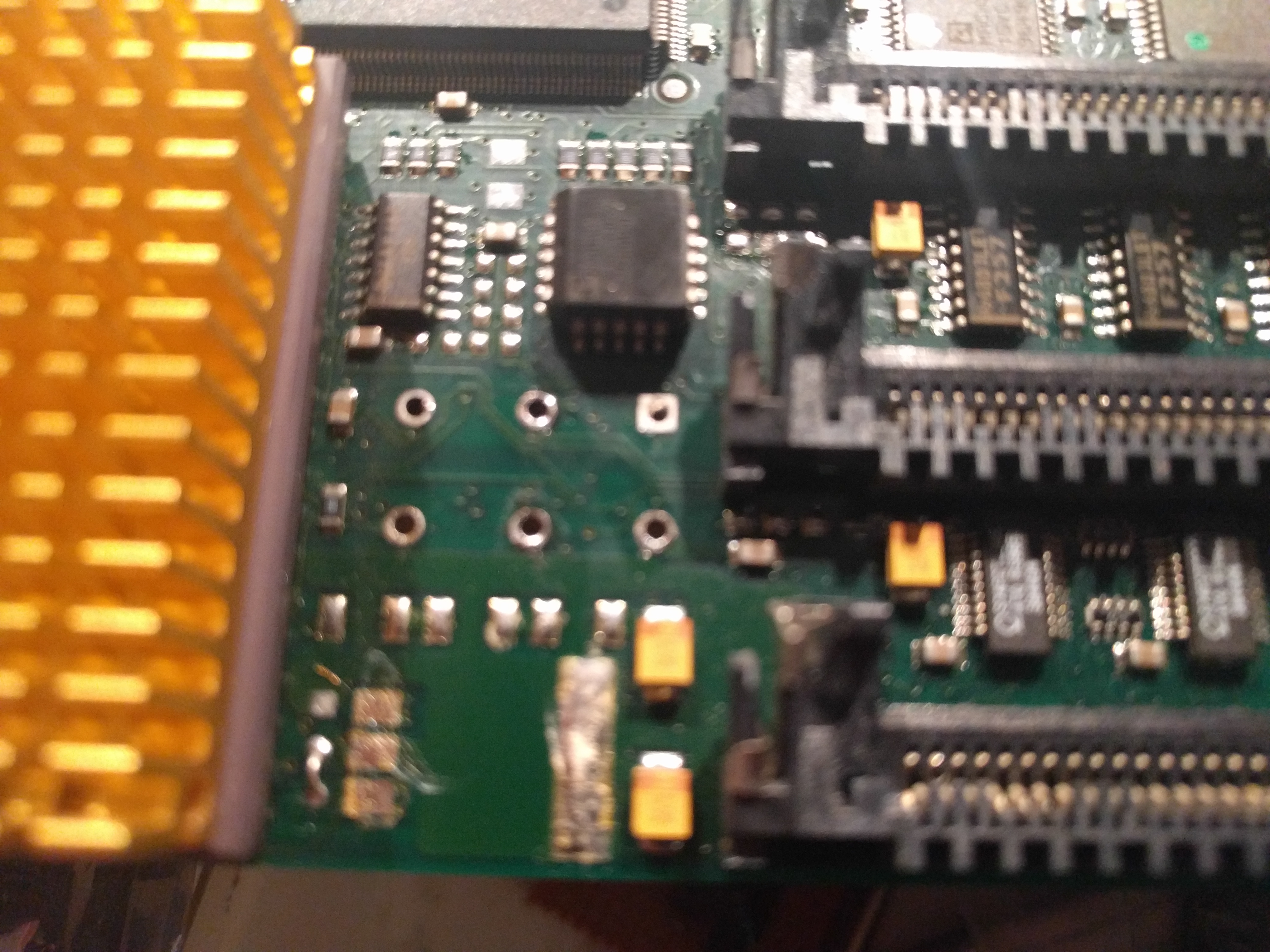
And as the holed are quite big, I could push in small socket-holders:
I decided to put in all 6 holes. so I can support both type of oscillators.
OK.
That was the easy part. now we have to change the voltage to the CPU. This is EXTREMLY important. failure if this WILL fry your cpu.
you will need one LT1085CM-3.3 voltage regulator 3.3Volts and three 1N4001 equivalent diodes. (some say that this is not needed..)
I found one voltageregulator in my drawers:
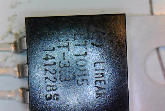
This is too big to fit, so first bend pins so you can solder it. and cut the pins. but the part with the hold need to be cut in half or it will simply not fit.
You will also need to change the oscillator. on this board it was soldered in, some seems to have sockets.
Well. the voltregulator-area on the 040-Board looks like:
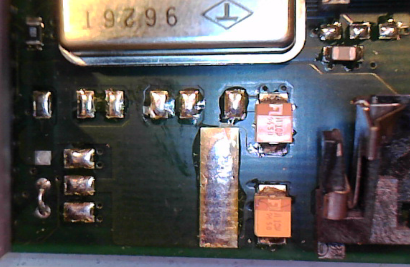
So here we see a small “wire” jumper that must be moved to the opposite location. Then solder in the voltregulator and diodes.

The diodes I had was slightly too large.. so not that nice here, but works fine.
Also notice the red little ring. you NEED to change that wire-jumper to that position, or you will send +5V into the CPU. and it WILL fry your CPU.
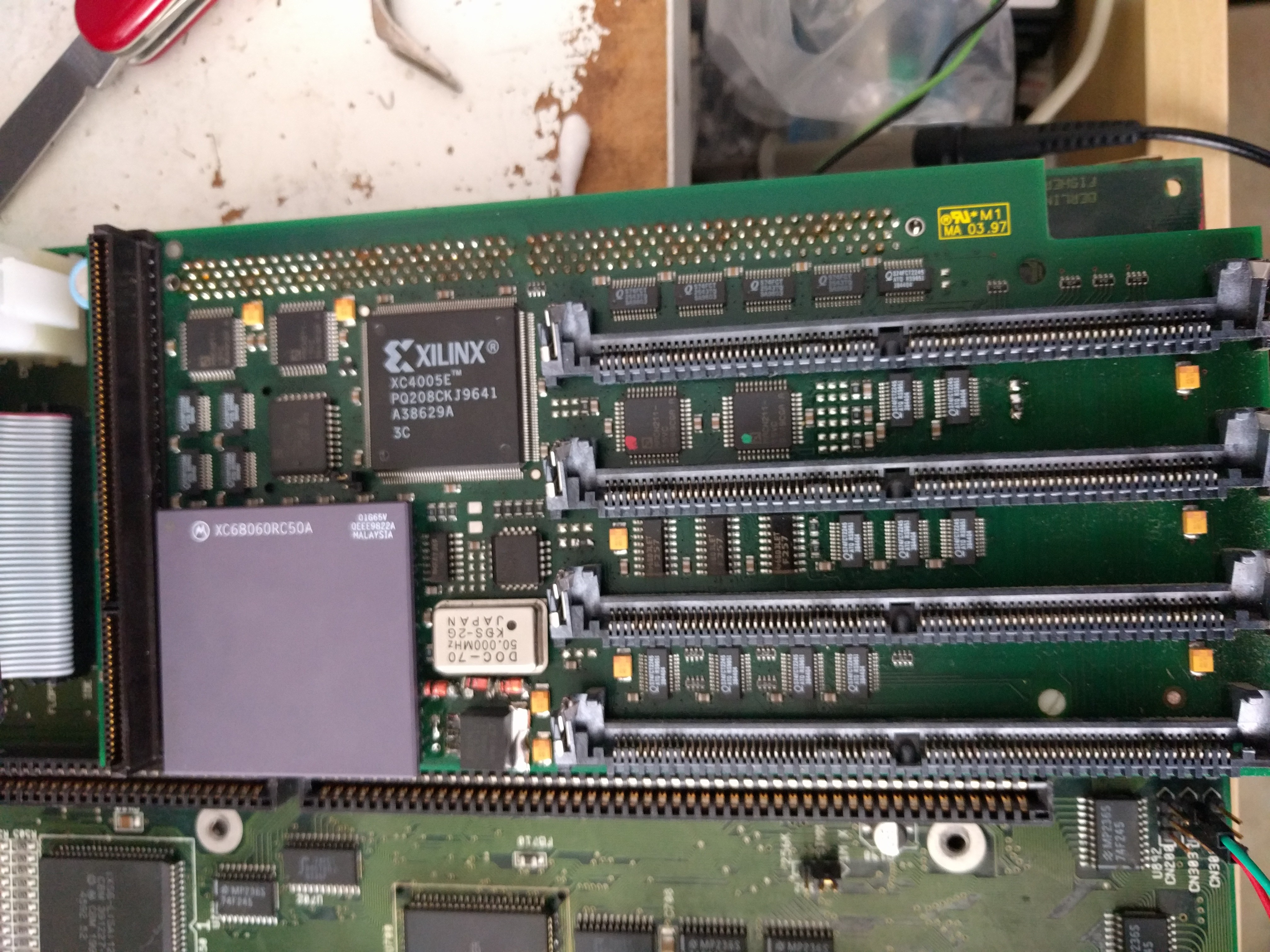
now change your CPU to a 060 one. Use a 68RC060 no LC or EC, even if they might boot, you will be wighout MMU/FPU and that is just plain wrong in a setup like this. (actually my machine crashed using EC when I tested) IF you can get hold of a Rev 6 (71E41J marking in the corner) USE IT! It runs very cool and can be overclocked a LOT!)
(on ebay.. WARNING there are a lot of fakes. many shows a Rev6 photo, but sends rev 0, 1 or 5)
You can also use a freescale version, no problem.
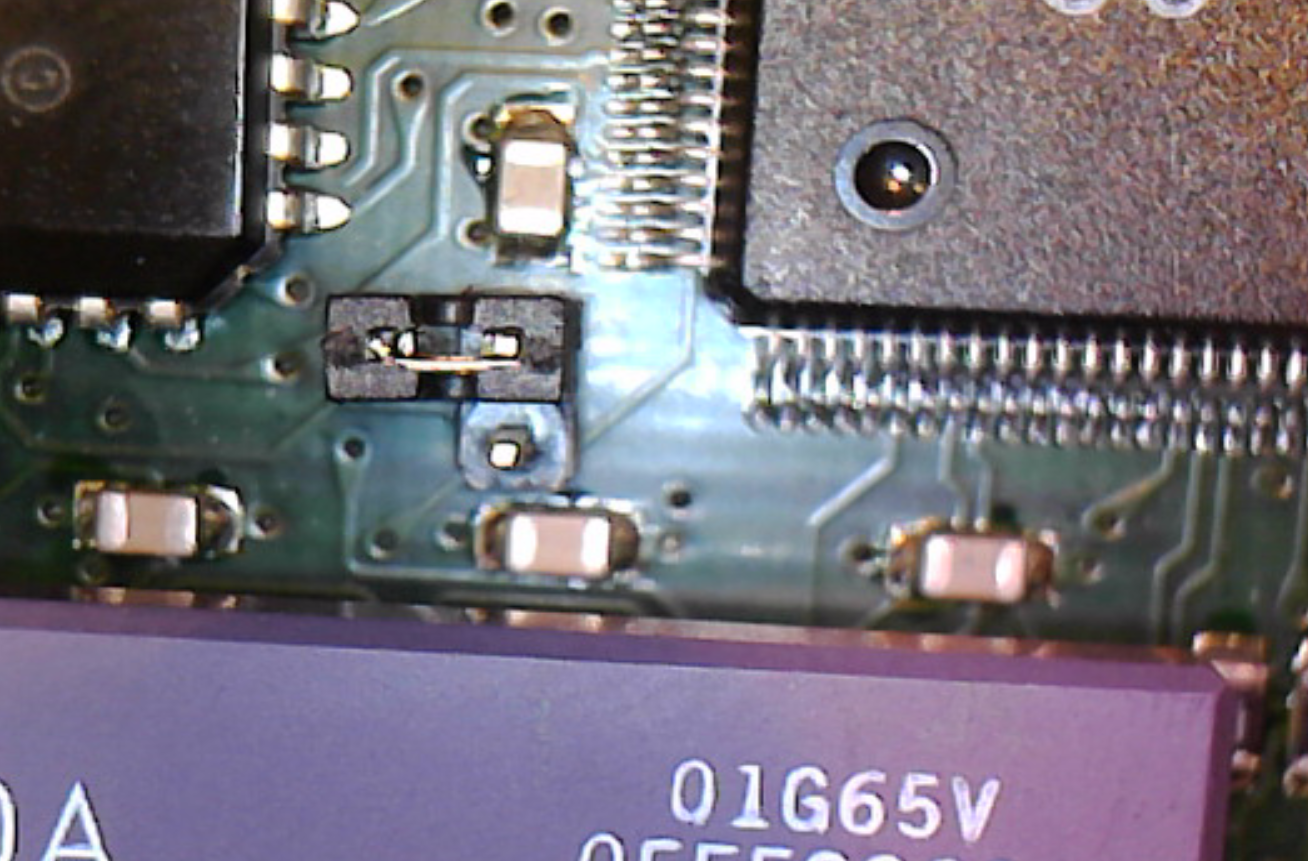
And last: remove the small jumper “above” the CPU:
Put in a oscillator of your needs (remember overclocking above 66MHz WILL make the SCSI Controller fail if you have one. and faster clock needs faster memory) test at 50MHz first, clock later.
Then your board would be somehting like:
Power on and:

IF You get a unstable machine etc. you first should check that you have the correct libs. I use the following files that I put in libs:
Have fun with your 68060.