Building the ReAmiga from scratch. Part2
Time to get some code running on this.
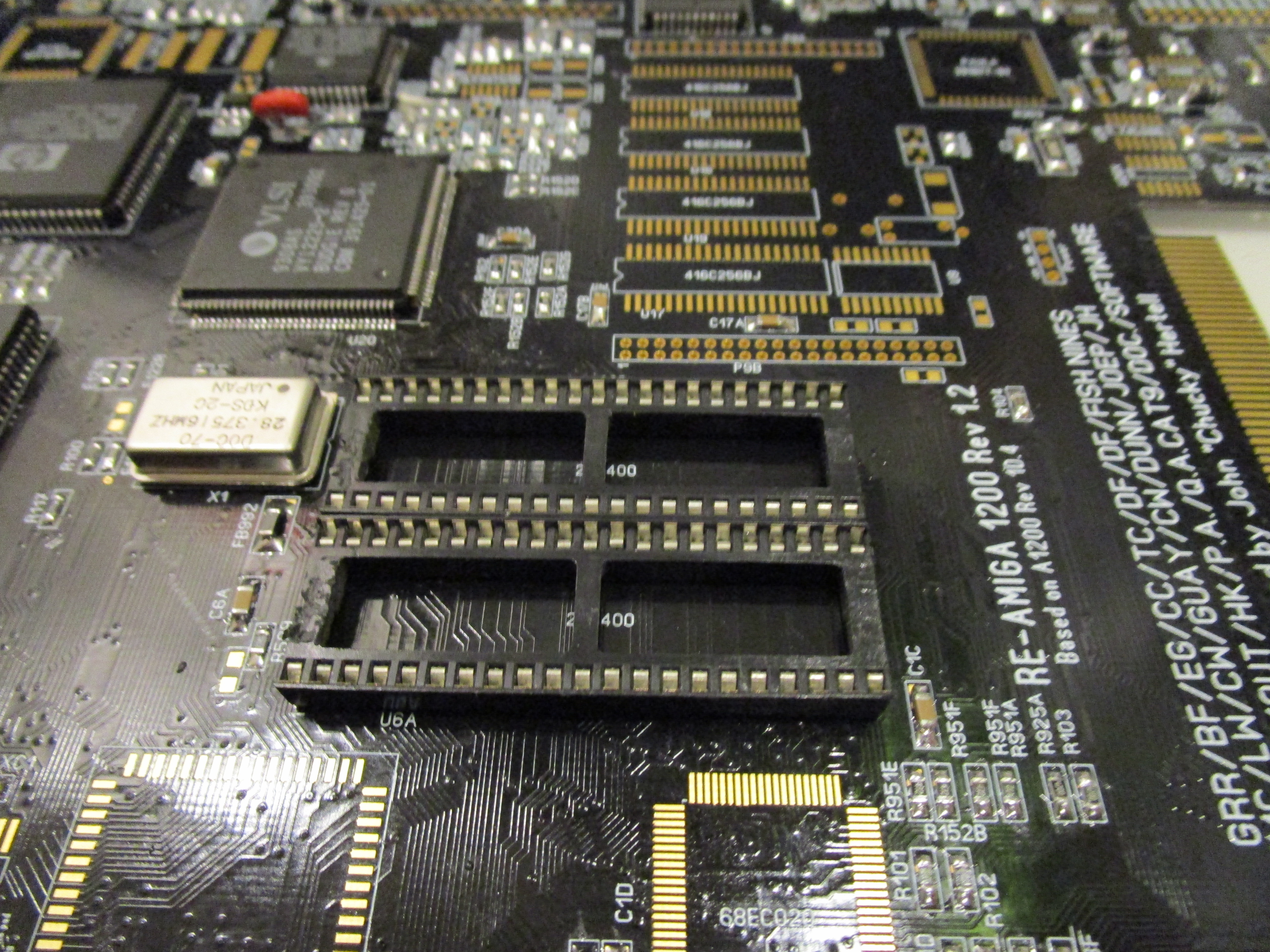
Time to get this board to a state that I call “minimum startup” it means this is the minimum population of components needed to get Diagrom to start.
First add the Keyboard MPU:
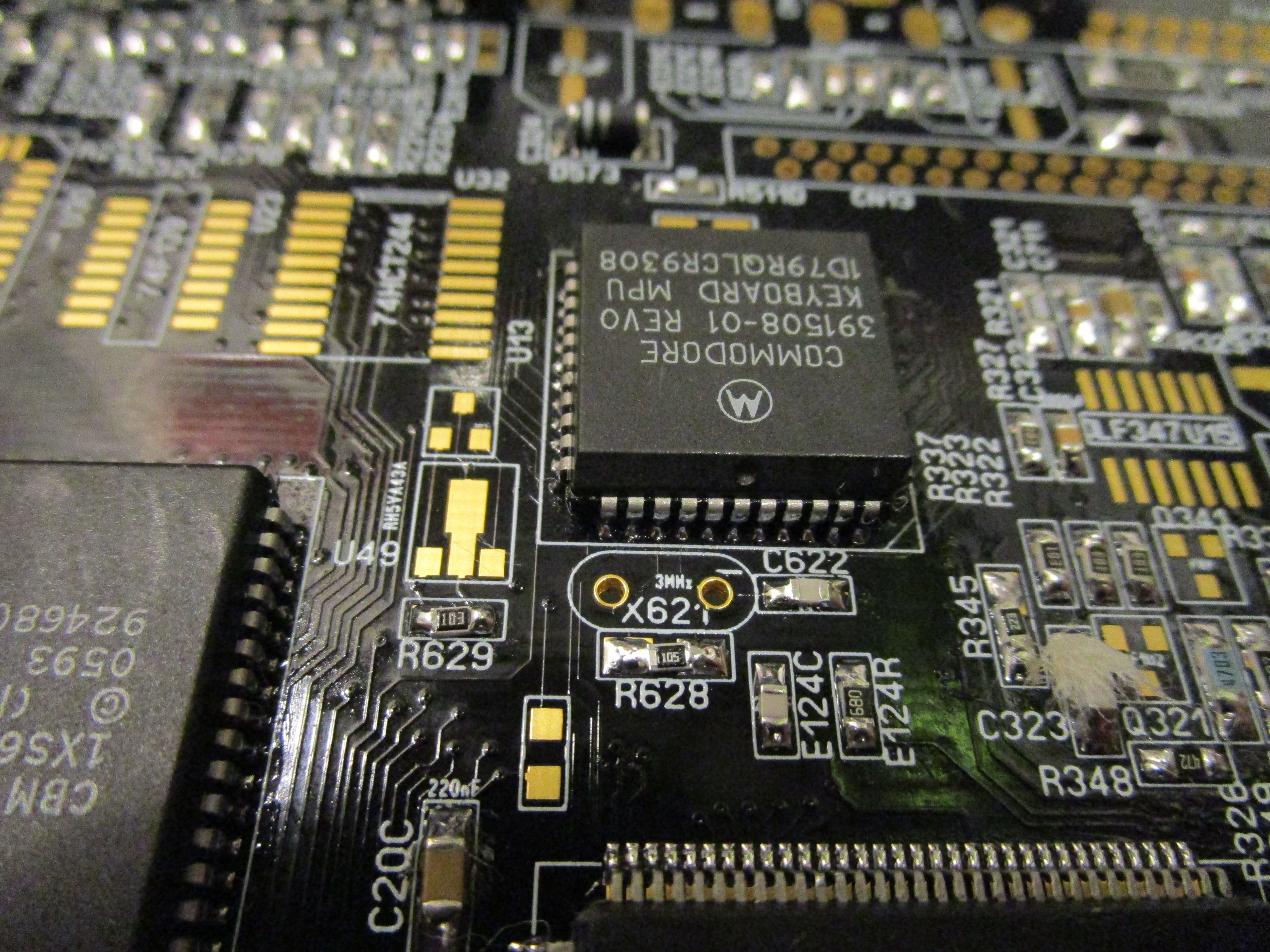
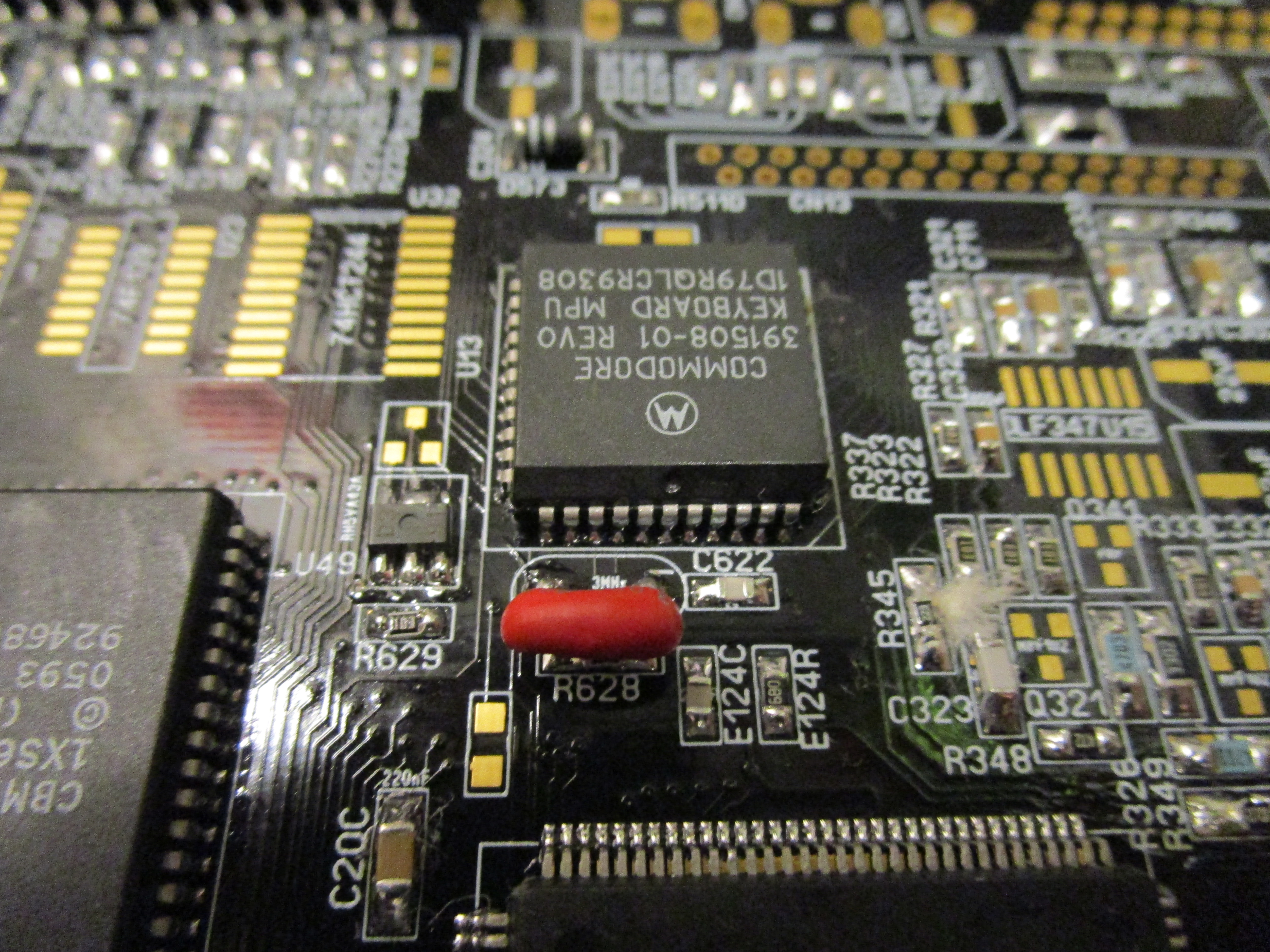
And then the 3Mhz resonator/oscillator (NO it is not a cap that some believes it is)
and the Low voltage detector. both are extremly important as the machine will not start without those.
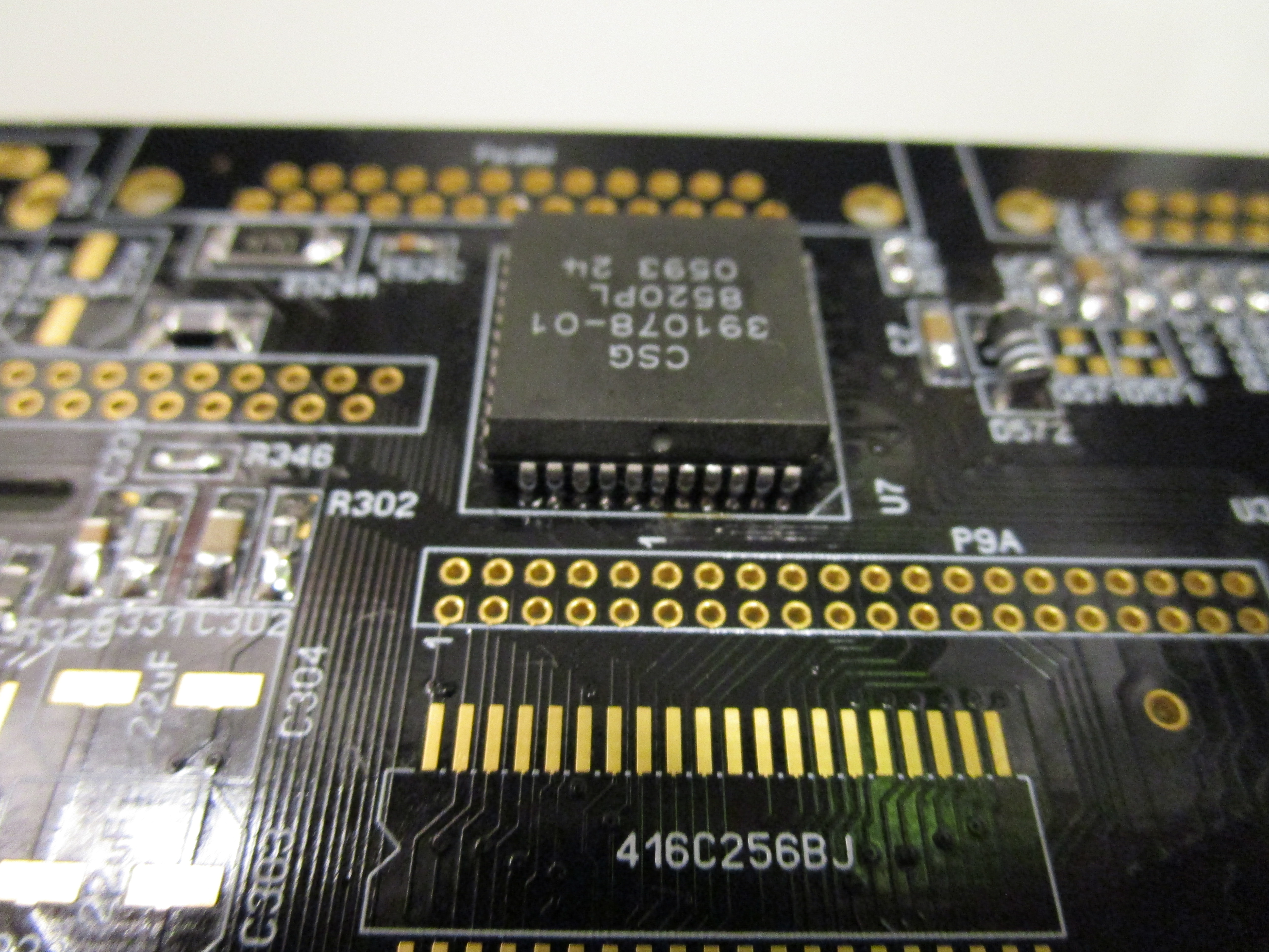
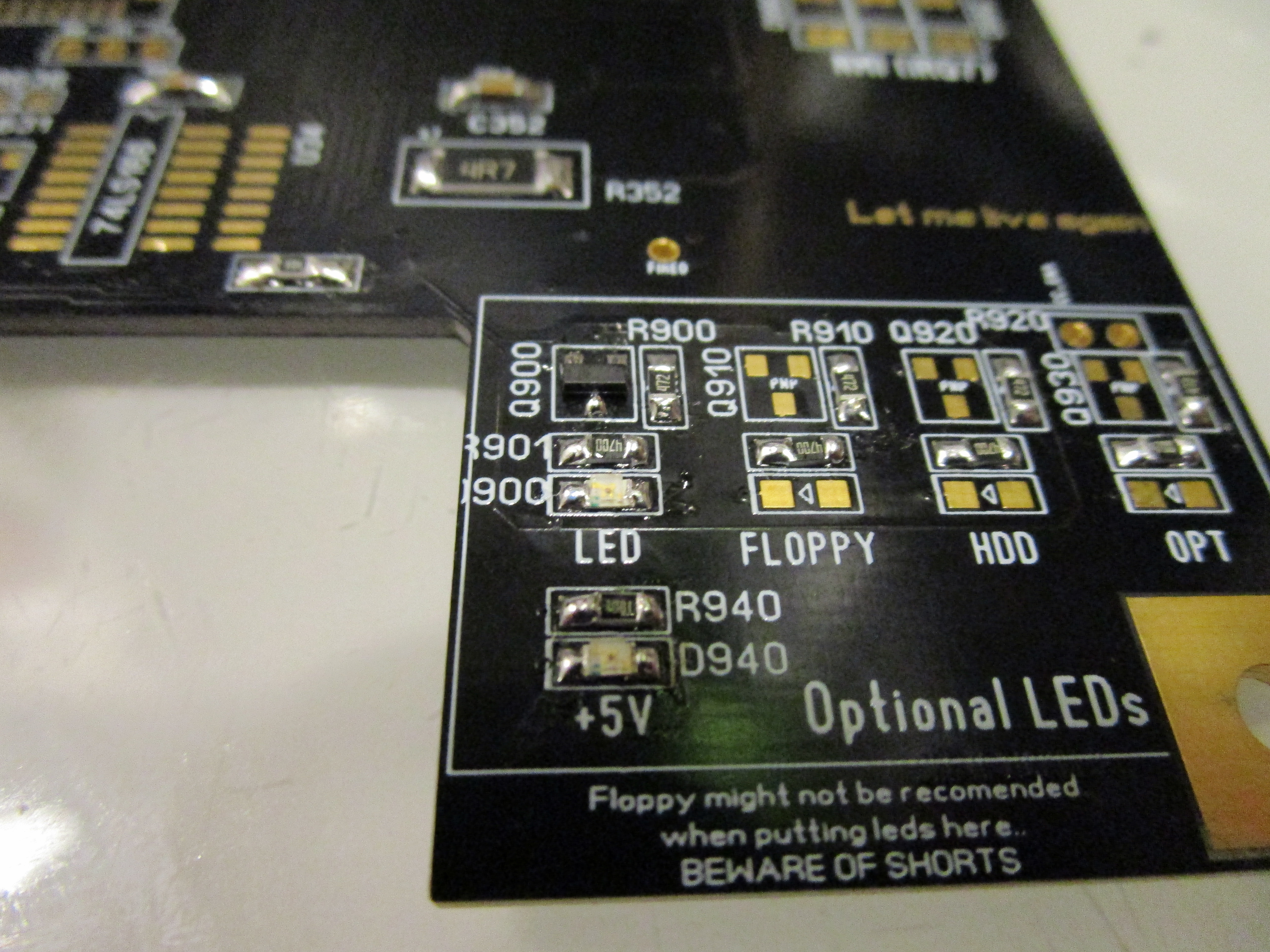
as our goal is to get the “LED” flashing. ODD CIA is needed. TECHNICALLY this is not needed to run the code. but to make it visible.
So lets add it:
Now to get ROM to be enabled. we need the GAL:
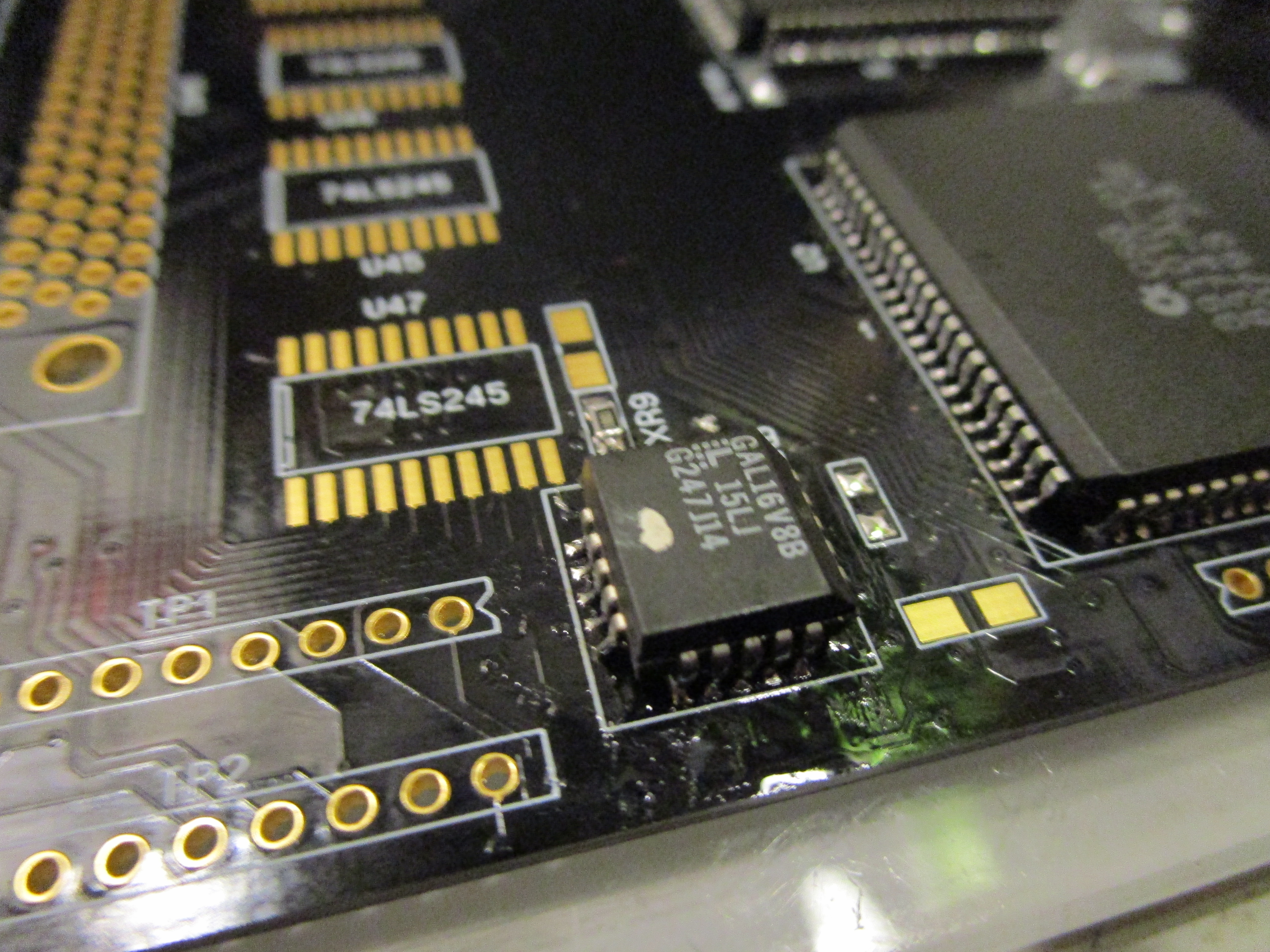
IF you are moving components from a Rev 2B PCB you CANNOT use the GAL from that board. it is for XU1, this is XU9. in the ReAmiga archive you will find the JED file for XU9. you need to have that programmed. or machine will NOT start.
And add sockets for the kickstart EPROM:
And time to add the led and the PNP Transistor needed:
Put 2 roms With DiagROM into the sockets (any version will do. but I do this post using DiagROM V1.1)
If you now put in a CPU card, the machine will start and you will see the LED flashing quickly:
if you have no fastmem on the board you will get a slower flash similiar to a guru. either way it should flash. if it doesn’t check your solderings. (most common issue is a bridge somewhere usually the budgie)
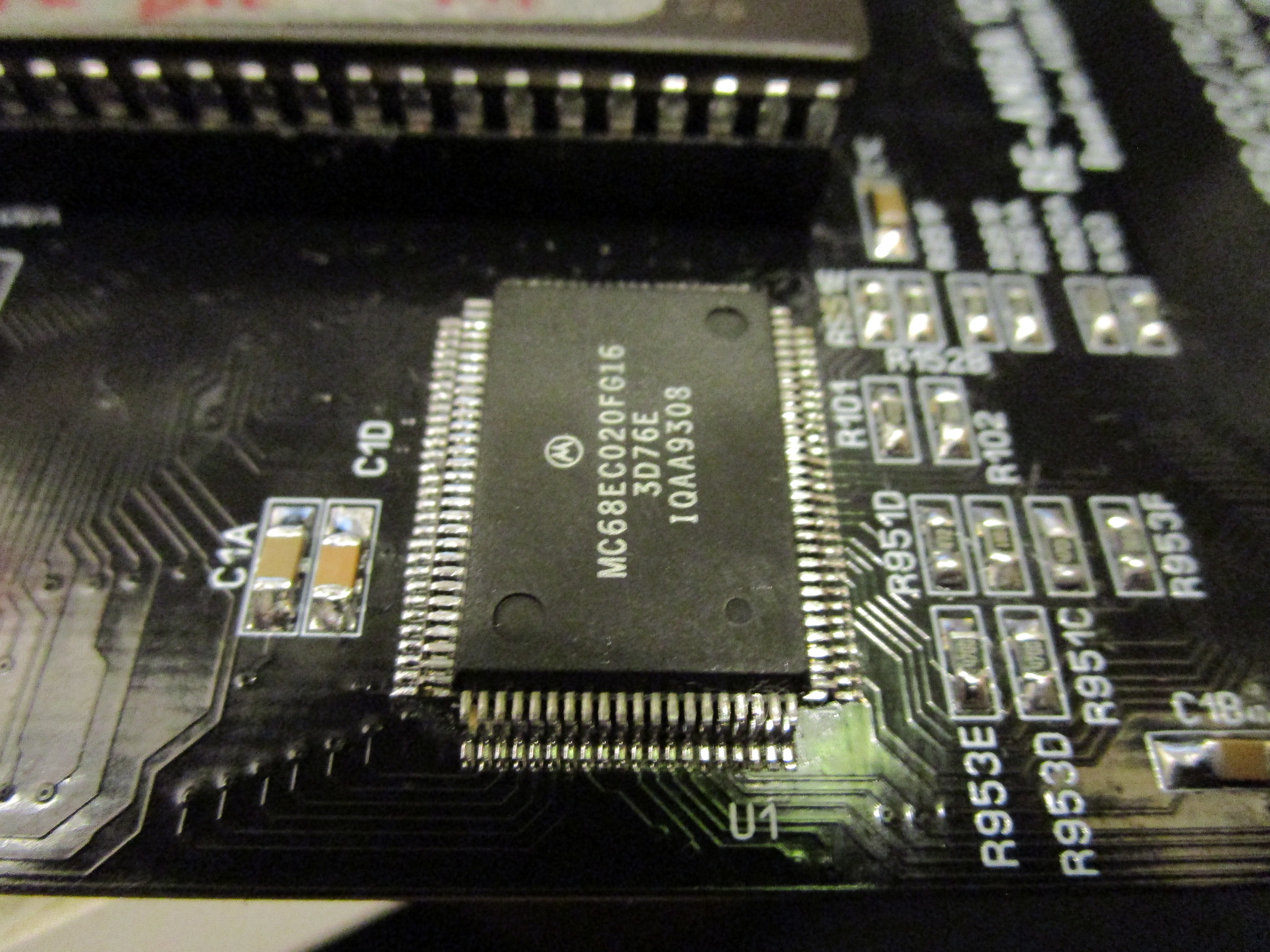
NOW add the CPU. the reason we did test without cpu is that the cpu is the hardest solder in this project. now with flashing led. we know that the minimal setup is working. if it doesn’t work with cpu. we can concentrate on that ut must be a issue with cpu or (most likely) a bad solder on the cpu.
Now turn on the machine. You will get a “guru” similiar LED flash. this as DiagROM will detect the paula as defective/missing. so it will skip serial output and chipmem detection will be done extremly fast. Putting the machine into “No mem found” mode, flashing the LED.
Now we will need a serial output to help us in the future. So to do that, lets add the PAULA and the Serial DSub. (25Pin Male):

This will however not be enough, we need to put in the 1488 Chip at U28 to be able to atleast SEND data to the serialport: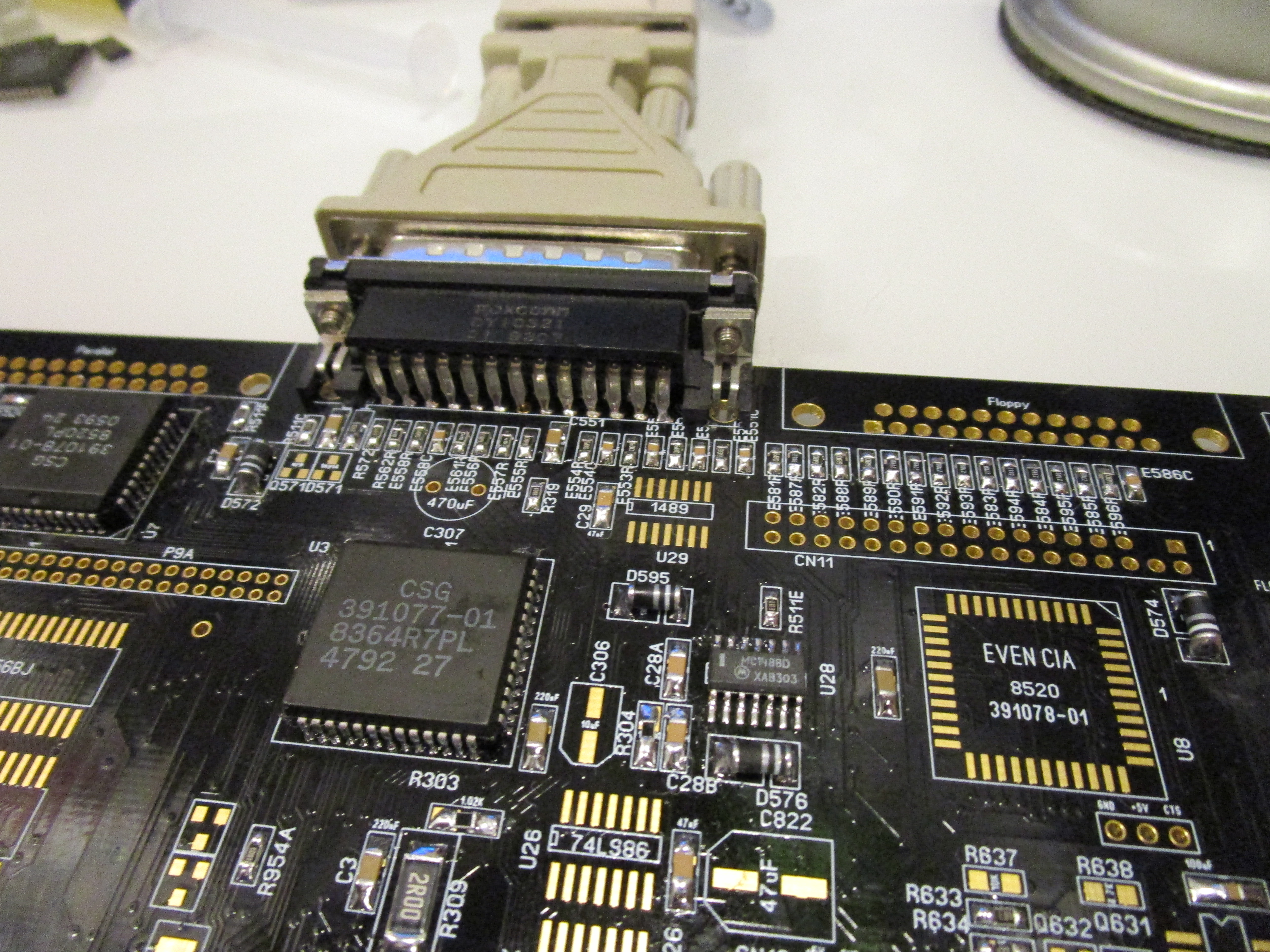
Now you need to connect a Null-Modem (DiagRom doesn’t use handshaking so TXT, RXD and GND is only really needed pins) to either another Amiga using NComm or so set to 9600BPS 8N1. or as I do, to my Windows PC using PuTTY. (via a USB Serialport):
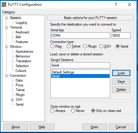
COM4 is my USB Adapter. set to 9600 BPS (and connectiontype Serial). and press Open.
a black screen will popup. and when you turn on your Amiga you should get:
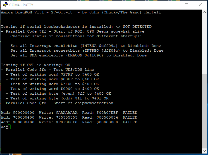
(and a memtest (that will fail) will be scrolling down the screen)
Your machine now starts diagrom. this is the point we will get things to start smoothly in next part.