Building the ReAmiga 3000 – Part 3 FINAL PART
OK.
Now we have a fully working ReAmiga 3000 except the Flickerfixerpart. This I wanted to take as a separate part.
I can point you to a very good guide here: https://www.tsb.space/knowledge-base/a3000-flicker-fixer-repair-and-adjustment/
First of all. I noticed that I had EXTREME issues in adjusting the trim-cap. I found out that if you put on all exctrolyte caps it works WAY better (I guess it is just those around amber that really is needed but hey. do them all) so first now. make sure you have installed ALL electrolyte capacitors, SMD as TH.
also! I noticed that one batch of my black pcbs seems to have a short to ground in the hole for the TH trim-capacitor, so measure the “bottom” hole to ground. if it is connected to ground you need to cut the trace between the hold and the SMD pad, also to the C499 capacitor, and run a wire:
here is a picture of the cut traces: (not the bottom traces cut on both sides of the hole)
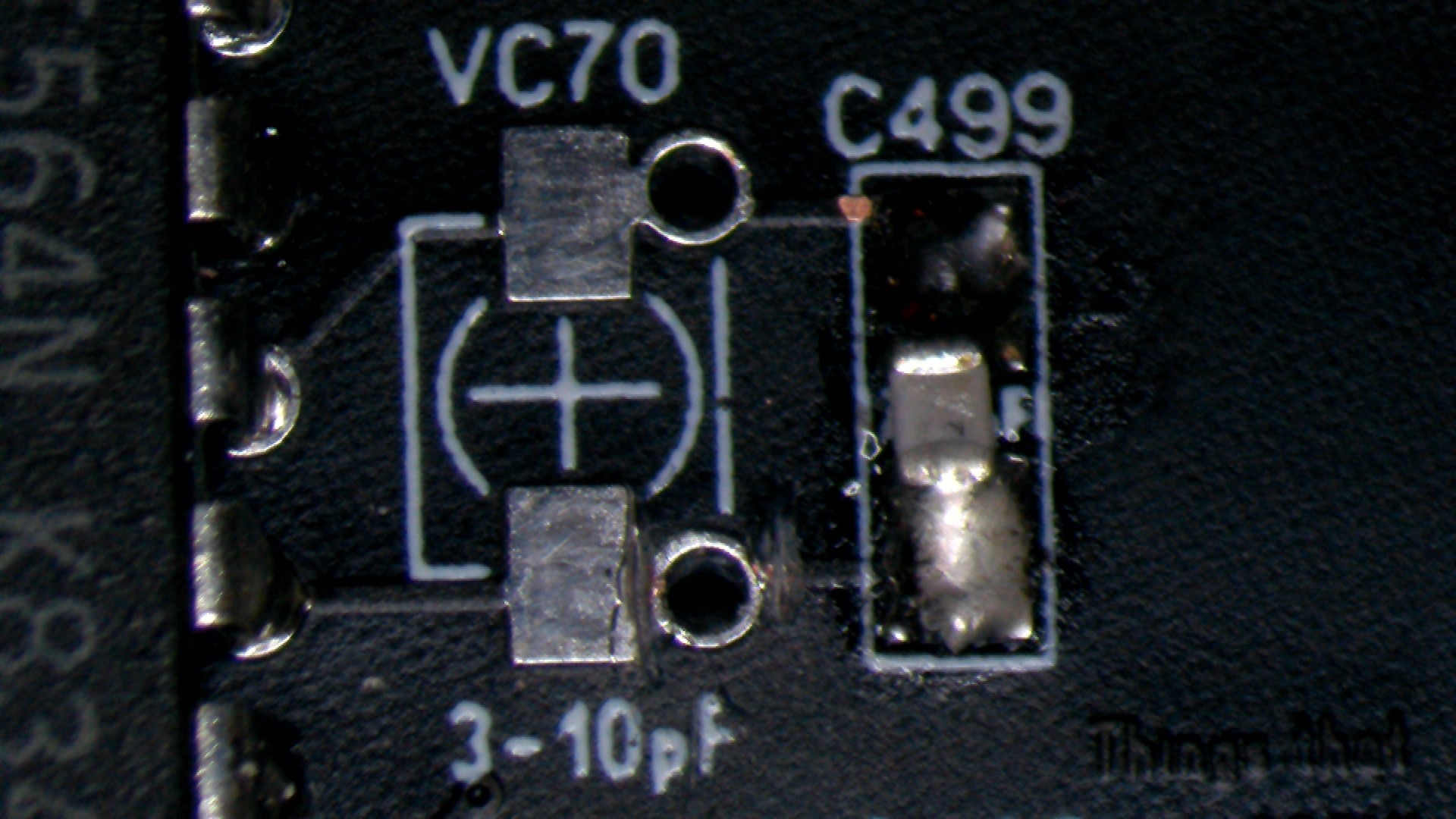
this also means you cannot use a Throughhole trimcap here!
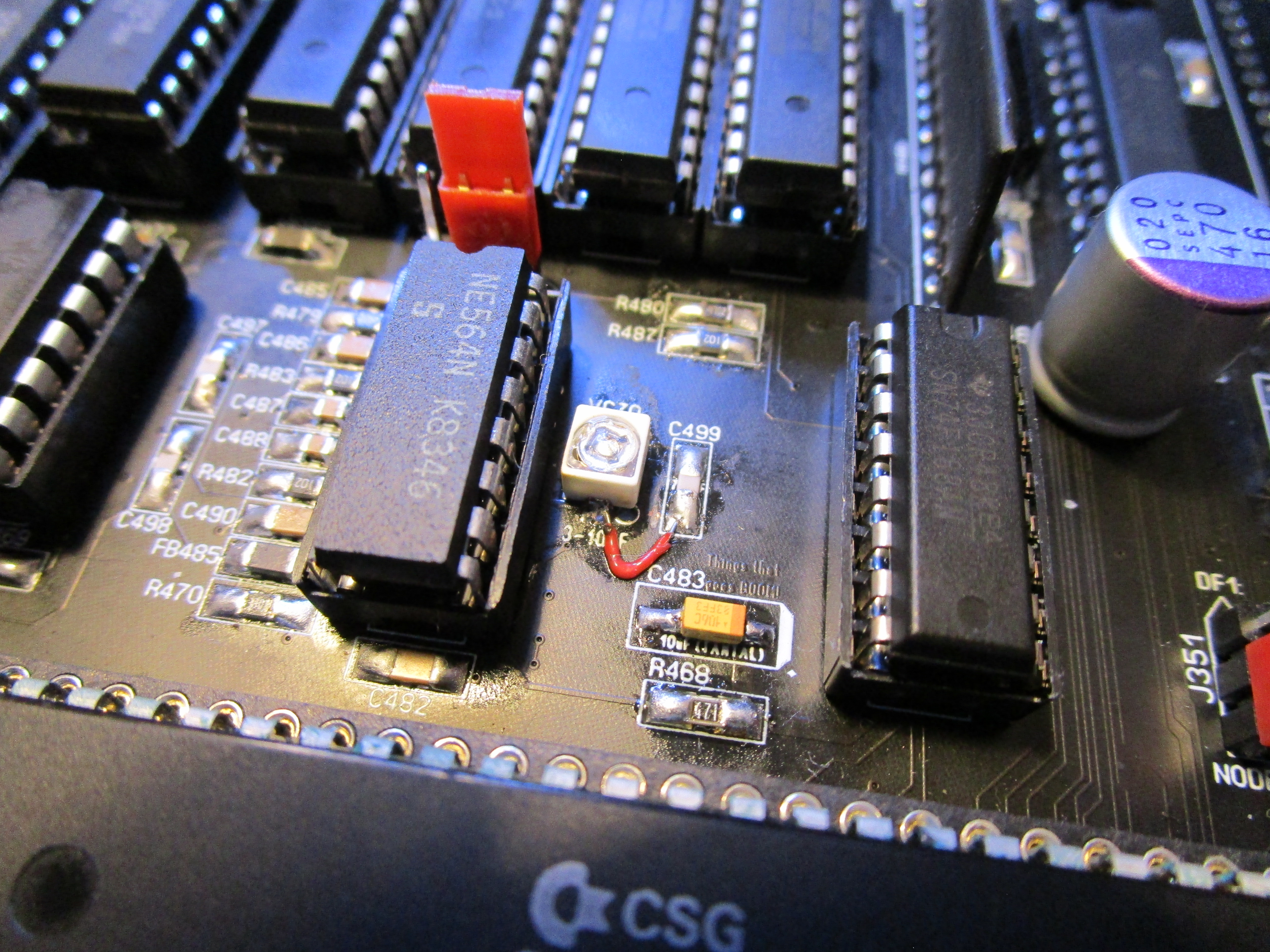
this is how it looks when installed:
Anyway. time to add the components:
Add U475, U473, U479 and U474 (uPD42101C-2) I use sockets as those chips are hard to get.. so less stress soldering them.
same with: U471, U470 and U472 (OKI MSM51422185-8)
also add U480 (72ALS74), U477 (74HC04), U476 (74F163) and the PLL U481 (NE564) I have it in socket but you might want to do it without socket. as it can be a reason why you do not get a sync. this part of the flickerfixer is VERY VERY sensitive.
Also add switch: SW481 and trim-resistor VR470 and the VGA connector. and Videot U478, text facing into the machine.
and finally the Amber.
also you need a 3-10pF trimmable cap at CV70 sometimes actually 3-15 can be useful)
now you can you can try to adjust the trim-cap and see if you can get a picture (using a PLASTIC screwdriver or you need to move the trimcap just a very little bit. remove and see if it syncs)
This is the result:

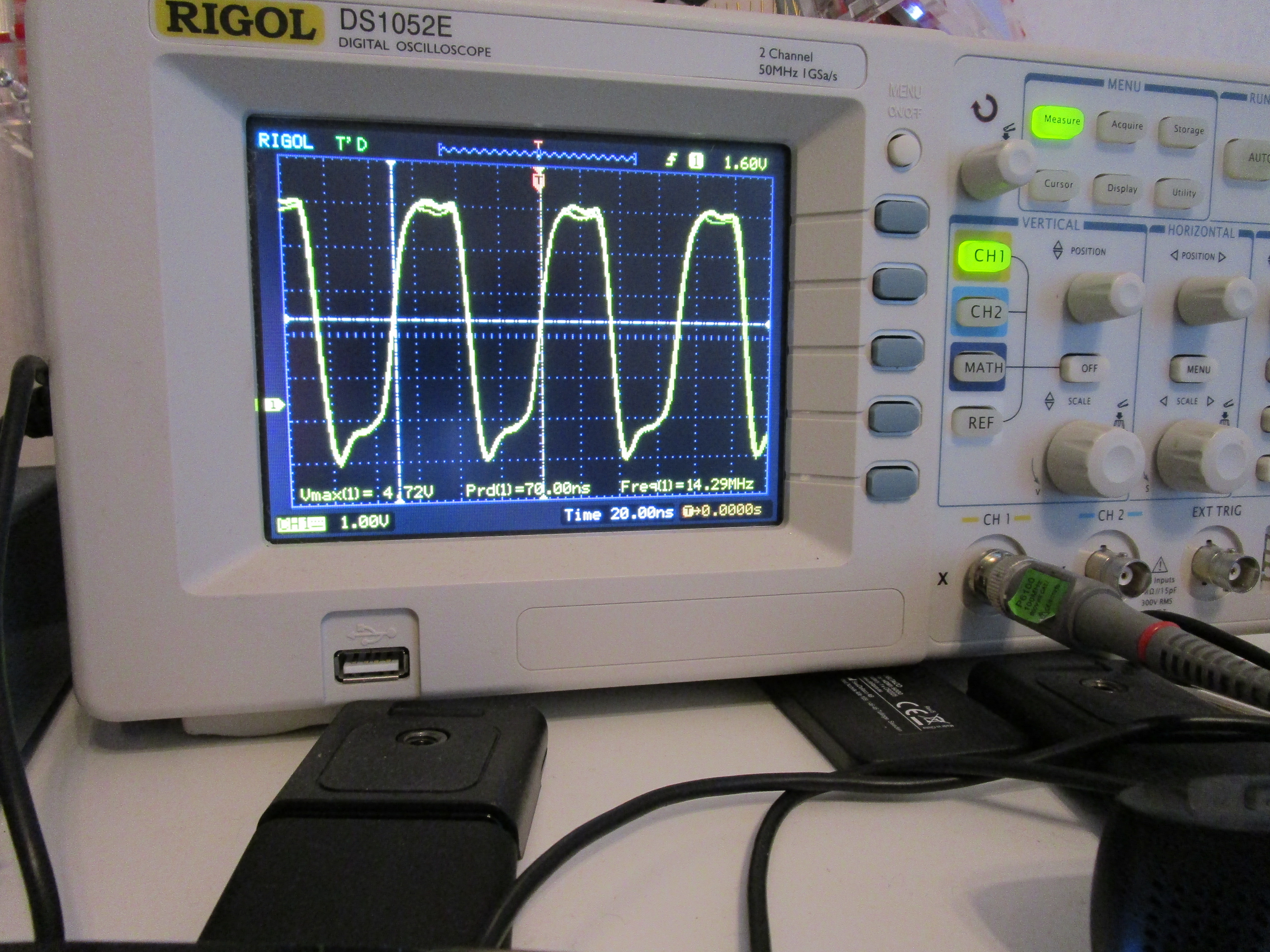
of you got an oscilloscope do measure the middle pin of the 3 pinheader to the left of Amber:
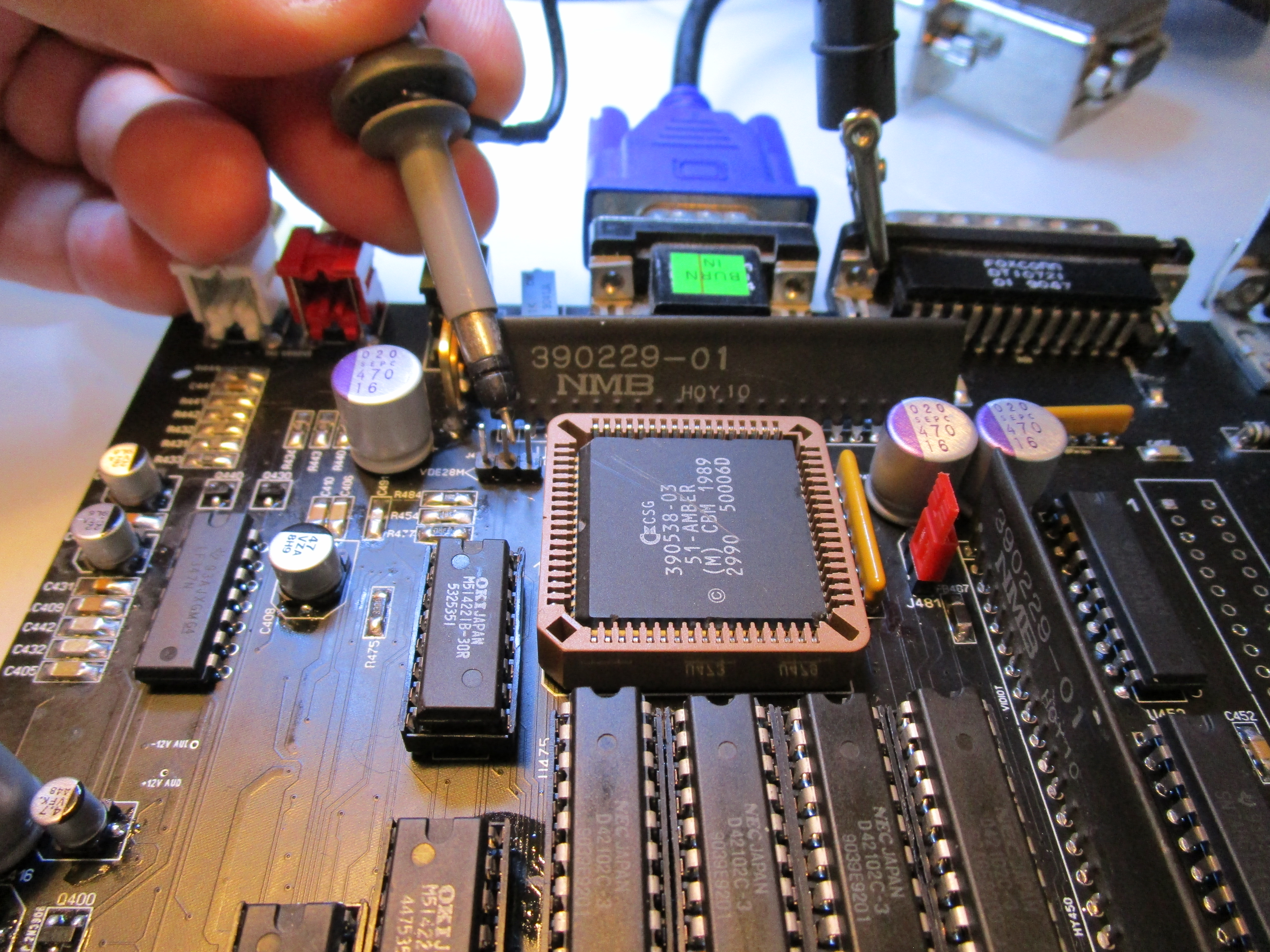
you should trimp the varibale cap so it measures something around 14.2MHz:
you can also do a finerune and measure the H-Sync from Amber:

do not push too hard damaging the socket:
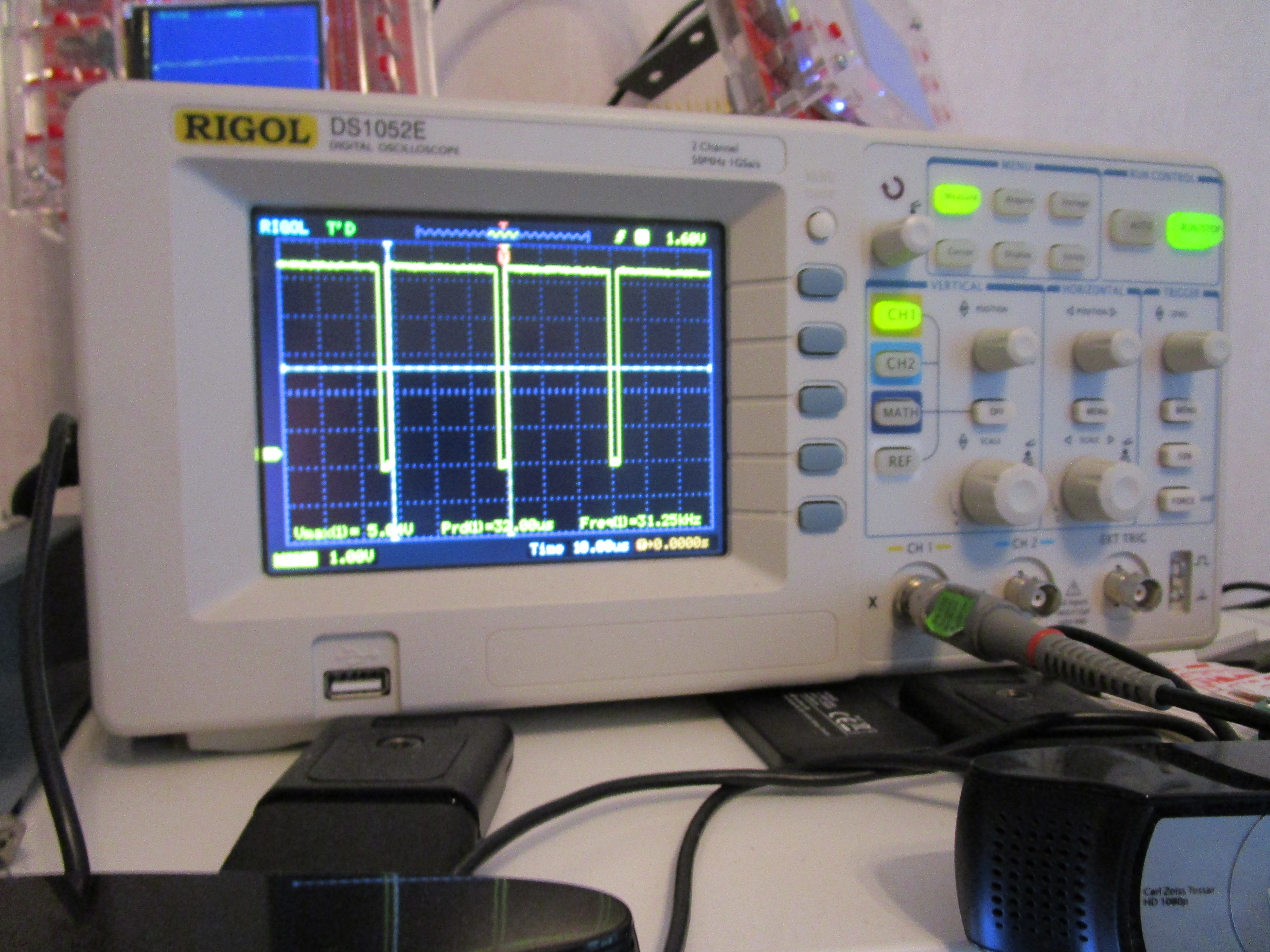
if the flickerfixer switch is in the bottom value you shold have 31KHz, and if you have trimissues you will see that the H Sync signal have ringing etc. you need to trim the cap until this stops. and it can be quite painful, no socket to PLL can help and sometimes the 3-10pF range isn’t enough..
also try with interlaced mode to see all is ok (use the link above for more information about this)
anyway. make sure all DB sockets is soldered and connectors and yo are all done.
SIDENOTE: if the SCSI led is soldered on the board. the external SCSI led to the case will not work. a small “whopsie” in the design. so remove the SCSI led on the PCB for it to work.
anyway.. Enjoy your machine:
